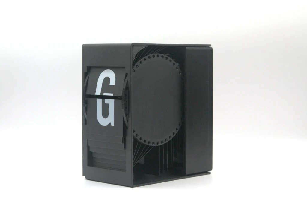
A current-version flip forward module consists of 8 printed parts, flaps, some fasteners, a small magnet and the electronics to make it all work.
In an earlier revision, 8 printed parts was the number of parts needed for just a section of the inner gears. There’s no inner gears anymore, there’s not even gears anymore – and that’s the lesson here.
The primary difference between split flap modules and pretty much any other project I’ve done so far is that ease of printing and ease of assembly directly impact project success: If one display takes an 12 hours to print and 2 hours to assemble, it’s just not feasible to build assemblies of 5, 10 or 50 modules.
So the focus is all the time on trimming anything away that can go away – and the equation is simple: The currency is complexity – and any part, screw, move during assembly needs to earn its place by directly making the display better.
I’ll give you an example. Until recently, the main drum assembly was held together by three screws that were screwed into threaded inserts that were melted into the plastic post-printing. While that’s extremely satisfying, it’s also time consuming and you need the threaded inserts. The original value proposition was that this will make the central drum more precise – but it really doesn’t. I’ve done versions with, versions without, and now there’s no more threaded inserts. Anywhere. They didn’t pass the test – not enough value for the complexity they’re adding.
There’s a strong connection I feel to changes in the software engineering world that are mostly about removing complexity, not adding new things – and the feeling of satisfaction that comes from that is just the same in hardware projects.
Are we done making flip forward modules as simple as they can be? Almost, I’d say. And to ground ourselves back in reality, here’s the latest simplifications and improvements:
Threaded inserts gone on the central drum and the back case.
Unipolar hall sensor replaced with omnipolar ones – no more finding the correct side of the homing magnet (that’s a huge quality of live improvement)
Added a small supporting flange for the 3D-Printed Front Case. helps with stability while not adding any meaningful print time.
The BYJ Motor Adaptor got replaced with a community version that is just.. much simpler!
I’d like to thank Richie and Daniel for their comments, suggestions and helpful feedback. This shaped a lot of the above and many more improvements – especially also on the documentation side.
You’ll find all the latest parts, along the build instructions and parts preparation over on www.flipforward.de.
There must be something about split flap displays. I can’t explain it any other way that there’s so many projects, companies, videos and repositories that deal with split flap displays. This post aims at collecting and describing them.
Publicly Available Designs / Open Source Project
Here are all projects that you can build yourself – because the instructions are publicly available.
This is what made it start for me. I think that Scott can be safely credited with building the most popular reference design and open source split flap display project.
The split flap modules you can build using his design are laser cut from MDF or Acrylic (including the central drum) and assembled using a a few M4 nuts and screw. And raw strength, as there’s quite some press-fit connections. They’re driven by a 28BY-48 motor – we’ll encounter that one rather often in this post.
He’s also providing the electronics, a system called Chainlink, that goes with the modules and makes bigger installations feasible and possible, as well as the option to buy ready-made flaps from his Etsy Store.
One of the outstanding aspects is not only the ongoing dedication he’s personally putting into this – the project has been going for over 10 years – but also some of the technical details. Most noteworthy is that the hardware is actually designed in OpenSCAD, a declarative CAD engine where you basically write your design in code. A very interesting rabbit hole.
Scott also has some videos that explain the basics of Split Flap Displays (well, most of it) in a lovely way, can highly recommend having a look at those.
This is a fully 3D Printed Split Flap Display that’s based on a design by Walter Greger with quite the community around it.
It’s impressive in multiple ways – the project contains a full set of multicolor, 3D Printable flaps (you’ll need a MMU or patience, but ideally both), build instructions and also ready-made firmware for a custom PCB (which is also part of the project).
My take is that this project has been fundamental in making split flap builds accessible to the 3D Printing crowd, and the use of available components – 28BYJ48 as a stepper, tons of filament and a few fasteners – really make for a very low entry barrier.
That is a real maker project – instructions are on instructables.com, and it’s basically just a wall of text and images. However, the hardware is a notch more refined than the other 3D Printed models. The case is especially not just functional, but looks designed with aesthetics in mind – and while it’s hard to put a finger on it, so does the whole project.
We’re again in the territory of the 28BYJ48, ULN2003 and so on when it comes to driving a motor: All open source displays with public designs use the same stepper and same electronics for driving them.
I stumbled over this one not too long ago – and it’s novel in many ways. It’s the first one I’ve seen using a (powerful) motor with a dual shaft – and it’s the first one that has PVC Drum sides that are cut with a water jet. It’s the first one that uses a sheet metal case as a default, and it’s the first one that comes with manufactured flaps and discloses where they are from.
It’s also the only design that I’m aware of that does a proper back panel with card edge connectors – Stefan really put a lot of energy into polishing all edges of this project. The result shows this. And look how happy he is!
Makers building Displays on YouTube for Fame
So this is an interesting one – there’s more than one person on YouTube that built a Split Flap Display without sharing their designs. That’s absolutely fine, I still want to mention them – since there’s always something to learn from every build.
Engineezy’s Score Counter Split Flap Display
So, that’s an interesting one. He set out to build a scoreboard out of split flap displays and started with a 28BYJ48-Based design, but then pivoted to using a much more powerful NEMA-type stepper. Since it’s not using a full alphabet drum, this seems to be overkill – but the combination of ideas that went into this design and the assembly is just nice to watch. Belt and pulley, NEMA Stepper, Laser Cut frame that ensures perfect alignment between the modules.
I highly recommend watching this, even if it’s just for the entertainment aspect.
Companies building and selling split flap displays
This is the most polished commercially available split flap display. It comes in two different form factors (Note and full size) and two different color ways – but always looks awesome.
After building many display modules myself I can safely say that if you want to have a working split flap display: This is the most economical, fast and beautiful way to get there.
The Oat Foundry is a US-Based company that is specializing in building and renting out commercial split flap displays. There’s nothing not too love about those folks – their showcases are jaw-dropping.
Unfortunately, their designs aren’t publicly available – understandable, but still a pity. From the visual appearance, it looks robust: Metal case, probably a beefy stepper on the inside and eye-catching animations. 10/10. Except for your purse, I guess.
Flip Forward
And there’s one more – flip forward, this project here. While the designs aren’t yet published, they will be – but you can already play with our virtual split flap display at play.flipforward.de.
Our design is based on a sheet metal frame, a NEMA-Type Stepper, Screen-Printed flaps and a sophisticated firmware and communication protocol that allows for seamless installations of small and large modules alike.
Anything missing?
If you’re building a project or selling displays and aren’t listed here – drop me a line!
The first ever flap for a split flap display I made was cut from a blank access card. I’ve still got it on a shelf here. The sound wasn’t great (more on that later), but it got me to the first idea of what a split flap display, one that can be built at home, might sound like.
I was once working for a manager who insisted that good decisions can only ever be those that are informed. Boring, pedantic, but true. So my first quest was to spend some money on purchasing an “O.G.” split flap display, and I got one from Bernd. I do not know where Bernd has those units from, but they’re authentic and in a good overall condition. I bought three – two to keep, one to slaughter.
The units arrived and they’re massive – at least in terms of weight, and also in terms of build quality. Something that’s built to last. And the flaps? Delicate. Super thin. Flexible. The polar opposite of a blank access card really. I’m not a material scientist – or a scientist, really – but my guess is that the flaps are made from PVC, with tiny holes cut or punched to have them mounted on the central drum.
Since I didn’t feel like going down the rabbit hole of driving the motor that they come with, I opted for the cheaper option: just using a screwdriver to actuate the drum. There’s a receptable for a hex driver on the side to do just that.
And if you imagine it was just me sitting there, with a screwdriver playing a human version of a motor and being entirely content with where I ended up in life: Spot on. That was a very wholesome moment.
What was next? Flex. Learning that a significant detail in what makes them work so reliably is not only the precise geometrics of where the drum aligns with the viewing window – that’s of course important. It’s that there’s a tiny amount of flex in the flaps just before they “turn over”, and that does two things: It ensures that they are always in the same position when a letter is viewed, but that also the “turn over” is happening both at the same position, and does so independent of the momentum of the drum. To illustrate that: In a display that purely depends on gravity for the flaps to fall down, you need something to provide at least some momentum, otherwise your flaps might be stuck in the wrong position. Usually, that momentum is provided by the drum moving, but especially for single character changes, that is just not a lot of momentum. And there’s a certain amount of friction that always needs to be overcome.
The magic solution here is to have flaps that can bend a tiny bit, and to rely on that in the overall geometry to have them flex, deform, just a bit before turning over. That way, there’s no outside momentum required any more, as the energy in the flex itself will ensure that the flap will turn over once it’s mechanical possible for this to happen. Magic – and so unexpected.
I made a video in an attempt to try and capture exactly that bend, that moment – and I’m sure you can spot it in the last clip.
Sound
One of the underrated features of split flap displays is that you heard when information changed: the characteristic rattle was a sure indicator that checking the departures board again might be a good idea.
There’s three things that influence the sound a display makes: First the sound generated between a flap and the case or guide inside the display. There’s always some friction, but ideally, this component shouldn’t be noticeable – unless you get something wrong (speaking from experience here).
The second is the sound that’s emitted from flaps interfacing other flaps. The significant moment here is when a flap falls down and the flaps that are already on the lower side basically brake the fall. This is creating the characteristic sound.
The third is the motor and mechanical system. I can’t judge this for my OMEGA-Module, but my assumption is that it wasn’t crazy loud – confirmed by standing beneath some operational displays and never noticing a motor sound at all.
Since the dominant sound is from the flaps interfacing each other when turning over, it’s only natural that the sound gets softer and less aggressive if you make the flaps lighter. After quite some experimentation, I ended up with using 0.4mm PVC as the carrier material, with the letters being screen printed.
And the good news? They sound great, and they also have very agreeable mechanical properties for the dynamic flex that is just so important for the whole module to work reliably.
When I look at the shelves on the other side of the room in which I’m sitting right now, I’m looking at things that did not work.
The first iterations of the display modules were not direct driven (with the motor being inside the drum), but were using a geared approach – one that I copied from an Omega Split-Flap module I bought on eBay. I spent so much time designing the gears, the overall assembly, tuning the firmware so that the stepper was able to overcome the friction – but it would never really work out reliably.
I added bearings. I tuned tolerances, observed very closely what happened on every iteration. Ultimately, the result was always the same: the displays were not reliable. Now the problem with that diagnosis is that, unlike with software, where I’ve got a very well tuned sense for right, wrong, fast and slow, I had no grip on what the reason for that was: incompetence and one or more oversights and easy to resolve issues – or a fundamental design issue that can only be addressed by pivoting to another approach?
Turns out, it doesn’t really matter why something is hard. If something is not a solution, but a rabbit hole: Move on.
The frustration of never being able to get a display running sustainably took away from the fun, the joy of working on this project over time. There was a sense of relief the very moment I allowed myself to depart from the “problematic” approach and just start over.
There’s countless instances where I had to do that – and it probably is amplified by the fact that this was a fun, but steep learning curve. When you have no idea how to do something, the chance to get it right the first time is rather slim. But you either get it right or you learn something, or both.
Looking back, there’s not a single thing that remained from the original “design” – and that’s a good thing. At the end, allowing oneself to pivot means two things: Being able to learn and incorporate new information, and still having the energy to throw something old away and start fresh.
Let’s state the obvious – Split Flap displays are incredibly easy to build. Rotating drum, some flaps (go paint them yourself), a motor and a case: voila!
There’s two complicating factors though: A single display element is really boring, it’s like eating a single french fry. Enough to get the idea, not enough to get the job done. And also, whatever you’re building doesn’t need to rotate once or twice correctly – and land on the same character – it needs to do so forever. Or at least often.
Meet: Endurance. The general idea is that I’m doing a simple acceptance test of the whole module, from electronics to the mechanics, and also the wear of primarily the flaps.
And the setup is remarkably simple. Every flip forward module is driven by an ESP8266 at its core, and thus can connect to WiFi.
On the other end is a Raspberry Pi that’s just going through the alphabet backwards, making sure that the longest path for each character change is used: Instead of going from A to B, which would just be a small number of steps, we’re going from B to A, which leads to an almost full rotation.
This display you’re seeing in the clip is somewhere at around 15k character displays, and I’ve had to do a few tweaks to reduce wear on the flaps – exactly why those tests are so important.
What I like is that it’s a rather easy way to get a lot of things validated and tested at the same time: From power delivery and energy distribution on the controller board over to the thermal characteristics of the stepper driver after running for a few hours to more subjective things like: How does this thing change its sound after a few hours (hint: it doesn’t).
And while it’s fun to see all of this rotating at full speed, there’s something even more satisfying about the slo-mo. Enjoy!
First steps don’t count if you don’t take them – and here’s to one.
flip forward is a project name, a working title. It might turn into more, it might not. Most of all, flip forward is a journey, one that taught me a lot of things about hardware, software, electronics and everything in between – but also a lot about me.
I made this blog to be my space to build in public. I’m too old for Discord, too educated for Twitter and too unpopular for Bluesky (but you can find me there, so it’s not for a lack of trying), so this has to do.
flip forward is about building split flap displays. Those old school funny-sounding displays that were omnipresent at train stations and airports. They got replaced by modern alternatives- I consider that a mistake.